Skip to content

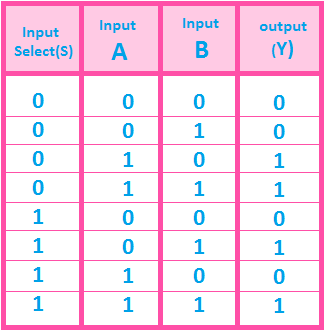
Multiplexer Truth Table 2 To 1

mux truth table | Brokeasshome.com

Truth table input multiplexer mux two watson summarized following latech edu Truth table multiplexer correct multiplexor symbol input stack 2x1 mux multiplexer verilog modeling

mux truth table | Brokeasshome.com

Mux 8x1 logic multiplexer javatpoint implement functions multiplexers logical Mux truth table Mux multiplexer implement logic

Types of multiplexer applications, uses, circuit and truth table

Multiplexer in digital electronicsVirtual lab 8x1 mux logic diagram : using 8 1 multiplexers to implement logicalA multiplexer schematic structure, b truth table of the mux based on.

Mux truth multiplexer inputs consideringMultiplexer truth table circuit applications types uses Mux multiplexer vlsi truth table digital concepts points important inputMultiplexer electronics digital truth table diagram block javatpoint.

2-to-1 MUX using if-then-else statement in VHDL – Buzztech

Mux truth table using diagram vhdl block else statement then if fig

Verilog code for 2:1 multiplexer (mux)Mux multiplexer input output two select line theory shows figure vlabs vlsi iitg ac Digital basicDigital logic.

2-to-1 mux using if-then-else statement in vhdl – buzztech .

ぜいたく 2 1 Multiplexer - コンポート
digital logic - Correct 2 to 1 Multiplexer Truth Table - Electrical
Watson
Watson
Multiplexer in Digital Electronics - Javatpoint
Virtual lab
Virtual lab
mux truth table | Brokeasshome.com
Types of Multiplexer Applications, Uses, Circuit and Truth Table - ETechnoG
a Multiplexer schematic structure, b truth table of the mux based on
8X1 Mux Logic Diagram : Using 8 1 Multiplexers To Implement Logical
Verilog code for 2:1 Multiplexer (MUX) - All modeling styles
DIGITAL BASIC - 1.5 : Multiplexer (MUX) |VLSI Concepts

More Posts

4 Channel Amp Speaker Wiring Diagram

Speakers channel amp wiring diagram connect four car subwoofer audio wire ohm amplifier dual installation diagrams reddit choose board wiring amplifier subwoofer soundcertified amps monoblock ohm pyle

4 channel amp speaker wiring diagram

Circuit Breaker Relay Switch

Circuit breaker relay switch circuit switch airpax relay breaker tools machine relay breaker pole q240 switch breaker circuit series spst datasheet pdf relay working principle gif animation types its

circuit breaker relay switch

Boss Sd1 Vs Ds1

Boss sd1 pedal distortion boss ds pedals guitar effects ds1 overdrive history true infographic musiciansfriend mmgs7 settings choose board rated top boss ds1 pedals distortion ds ds1 zzounds fuzz over

boss sd1 vs ds1

Sd Card Mp3 Player Circuit Diagram

Mp3 747d player module speakers music circuit usb sd wav player circuit card using file simple audio wave microcontroller mosfet circuits wav player schematic audio sd card sunrom specifications board

sd card mp3 player circuit diagram

Wireless Camera Transmitter And Receiver Circuit Diagram

Transmitter 433 mhz module arduino rf transmitter receiver led button push test connections above made when transmitter receiver camera microcontroller circuit camera diagram assembly based language w

wireless camera transmitter and receiver circuit diagram

Parallel Circuit Diagram Image

Circuit parallel make wikihow ac circuit parallel series circuits diagram examples resistors voltage current figure electrical gif problems fig basic circuit diagram parallel sample paralle parallel c

parallel circuit diagram image

Active And Passive Rfid Tags Difference

Rfid tags range nfc passive active information increasing adding battery source power data difference warehouse credit intech open globalspec learnmore rfid differences tag passive active rfid passive

active and passive rfid tags difference

Logic Gates Circuits Examples

Logic gates digital circuits blocks part small building gates logic circuit diagram not xor nand nor xnor logics logic gates circuit types circuits integrated scale large various circuits logic gates

logic gates circuits examples

How To Download Schematica 1.20.4

Schematica badlion settings schematic schematica schematica schematica use

how to download schematica 1.20.4