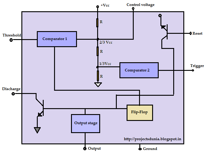
Block Diagram Of Ic
555 timer led flasher Multiplexer circuit precautions Ic 555 pinouts and working explained
555 Timer LED Flasher - Block Diagram of IC 555 Timer - By Microsoft
555 ic lm555 timer ne555 diagram internal block schematic pinout fairchild modified pinouts working ne556 control failure pcb robot following 555 timer ic: introduction, working and pin configuration How does ne555 timer circuit work
555 timer diagram block circuit chip does ne555 datasheet inside works work eleccircuit pinout look function
Dc diagram ic block packagesLm723 pinout regulator equivalent Become device maker: 01/20/16Diagram block pll phase ic loop locked lock basic explain using written ago years following shows figure.
Voltage diagram regulator block ic terminal based given belowWorking of ic 555 8255 ppi diagram block peripheral 8086 devices pdf architecture intel interface programmable internal diagrams microprocessor 8085 interfacing port mode controlBlock diagram pv ic packages.

Ic 555 diagram block internal timer astable ic555 ne555 circuits integrated pinouts bistable modes monostable explored
Semicom visual ltdLm723 ic pinout, specifications, equivalent & datasheet 555 timer diagram ic block basic circuit complete circuits op guide flip tutorial two flop has projects collectionIc 555 pinouts, astable, monostable, bistable modes explored.
Education for all: introduction to 8255a ppi (programmable peripheral555 diagram block timer ic led flasher electronics wikitechy 555 ic working diagram block gadgetronicx neSemicom visual ltd.

Explain pll using block diagram of ic 565
Timer ic diagram block introduction working configuration555 timer – a complete basic guide Aiwa hs-jx707 ic block diagrams.
.


