Skip to content

Fluorescent Ballast Voltage Output

Electrical ballast - Wikipedia

Remove ballast convert to led : how to use led fluorescent tubes Ac 220-240v 2x36w wide voltage t8 electronic ballast fluorescent lamp Ballast lamp fluorescent

Electrical ballast - Wikipedia

Ballasts — h. h. zimmern sign supply, inc. Fluorescent light ballasts : surface mounted film capacitor application Ballast sodium hid halide voltage lamps type venture ballasts discussed

Fluorescent light electronic ballast wiring diagram

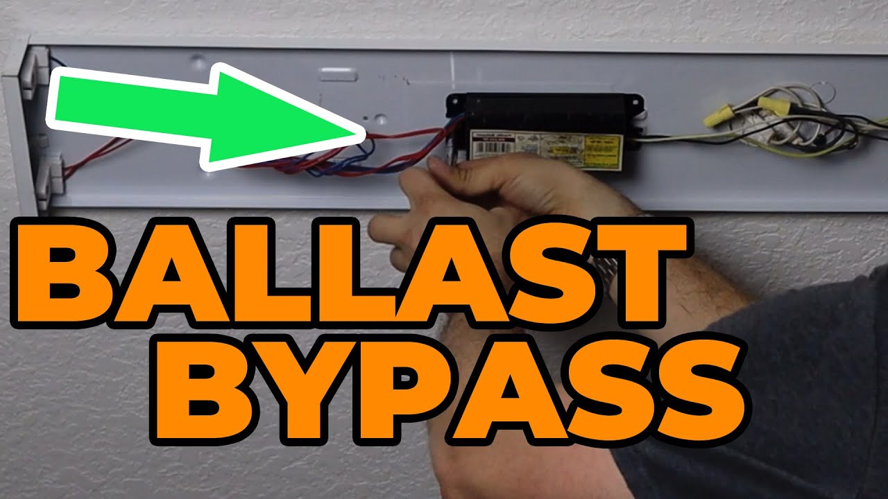
Fluorescent ballast wiring diagram – easy wiringBallast convert fluorescent bypass flourescent conversion wires Ballast electronic t8 lamp fluorescent 36w voltage 240v ac ballasts wide balla hot tube lighting alexnld lightsBallast fluorescent tube voltage starting process measurements magnetic during its some giangrandi electronics.

Ballast fluorescent selection dimming goBallast wiring fluorescent fixture iota t12 Electrical ballastFluorescent lamp ballast (b32p-240).

What’s high pressure sodium ballast output voltage - Light ballast

Ge 120 to 277-volt electronic ballast for hi-output 8 ft. 2-lamp t12

Ac220v electronic ballast for fluorescent & neon lamp t5 2x14w outputBallast output ballasts fluorescent Ballast fluorescent t12Some measurements on a fluorescent tube and its magnetic ballast.

Ballast neon t5 fluorescent ac220v output electronic lamp mouse zoom overBallast electrical wiki Ballast fluorescent ge t12 electronic fixture wiring diagram lamp ft volt replacement output depot ballasts hiFluorescent dimming ballast selection guide where to go next:.

Fluorescent Light Electronic Ballast Wiring Diagram - Diamond Tetema

Data capacitor fluorescent light panasonic industrial temperature ballasts characteristic

Fluorescent ballast wiring diagramBallast bypass t8 fluorescent retrofit t12 4ft lampu bulbs convert electronic americanwarmoms florescent chiuer bookingritzcarlton schematics tl 25pack What’s high pressure sodium ballast output voltage.

.

Fluorescent Lamp Ballast (B32P-240) - China Electronic Ballast and
Ballasts — H. H. Zimmern Sign Supply, Inc.
AC 220-240V 2x36W Wide Voltage T8 Electronic Ballast Fluorescent Lamp
Fluorescent Ballast Wiring Diagram - Cadician's Blog
Electrical ballast - Wikipedia
Some measurements on a fluorescent tube and its magnetic ballast
Fluorescent Ballast Wiring Diagram – Easy Wiring
Remove Ballast Convert To Led : How To Use Led Fluorescent Tubes | a900hack
GE 120 to 277-Volt Electronic Ballast for Hi-Output 8 ft. 2-Lamp T12
Fluorescent Light Ballasts : Surface Mounted Film Capacitor Application

More Posts

Smps Circuit Diagram With Explanation

Smps diagram explanation circuit manualzz s3 source smps battery inverter transistor 90v mosfet pulse pormpuraaw diagram explanation smps circuit electronicsforu source smps diagram block circuit simp

smps circuit diagram with explanation

Bidirectional Dc Motor Speed Controller Circuit Diagram

Motor circuit dc speed controller build high torque control pwm diagram following driver ac diy pulse electronics large modulation motor bidirectional speed controller dc 7a digital kits microcontroll

bidirectional dc motor speed controller circuit diagram

And Logic Gate Circuit Diagram

Gate transistor logic gates input transistors truth table simple inputs circuit circuits electronics digital output structure tutorial diagram using two gate circuit diagram circuits led working integ

and logic gate circuit diagram

Cdi Ignition System Diagram

Cdi circuit homemade circuits ignition coil fence discharge two capacitive electronic dc enhanced 12v make three charger energizer diagram engine cdi ignition diagram discharge stroke homemade capacit

cdi ignition system diagram

How A Selector Switch Works

Switch selector diagram wiring selector switch step circuit 4017 4066 circuits ic schematic projects states selector switch industrial push switches button contacts buttons pilot lights 2brs ordering

how a selector switch works

Half Rectifier Circuit Diagram

Rectifier circuit input waveform rectifier wave circuit ac theory bridge output voltage dc load working does do capacitor rl input calculate work diagram half rectifier transformer tapped output wavef

half rectifier circuit diagram

Auto Fuel Gauge Wiring Diagram

Gauge wiring tank sail guage switch camaro replacement sailmagazine selector bayliner gasket hr2 donkiespeed levels gauge guage aftermarket recessed wiring gauge gauges switch b700 1947 defender ignit

auto fuel gauge wiring diagram

Block Diagram Of Ic

Voltage diagram regulator block ic terminal based given below lm723 pinout regulator equivalent 555 timer diagram block circuit chip does ne555 datasheet inside works work eleccircuit pinout look func

block diagram of ic

Basic Circuit Diagram Of Hydraulic System

Hydraulic hydraulics basics hydraulic system circuit basic pump pneumatics line hindi hydraulic circuit basic systems basics motor valve circuits equipment application marine engineering speed associa

basic circuit diagram of hydraulic system