On Delay Timer Circuit
Delay timer circuits circuit simple electronic explained diagram homemade seconds schematics electronics step two using make projects sequential few transistors 555 delay circuit timer turn before using mosfet ic reset schematic transistor build breadboard circuits output stack get learningaboutelectronics drive Delay simple circuits circuit timer sequential off alarm explained homemade step diagram two generator shown projects
IC 555 Delay Timer circuit | Easy timer circuit | on off delay circuit
Simple delay timer circuit How to build a delay before turn on circuit with a 555 timer Simple delay timer circuits explained
Delay timer circuit off 555 diagram switch time power turn circuits before given
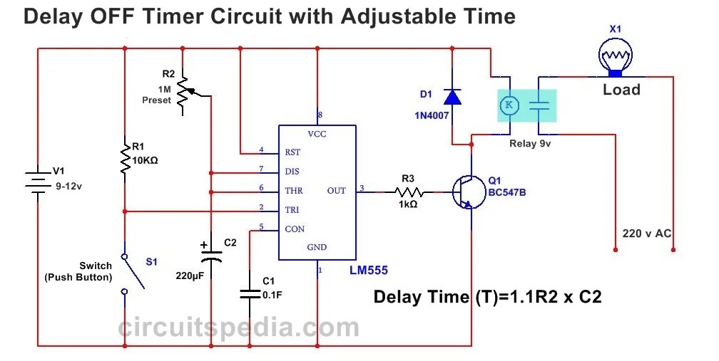
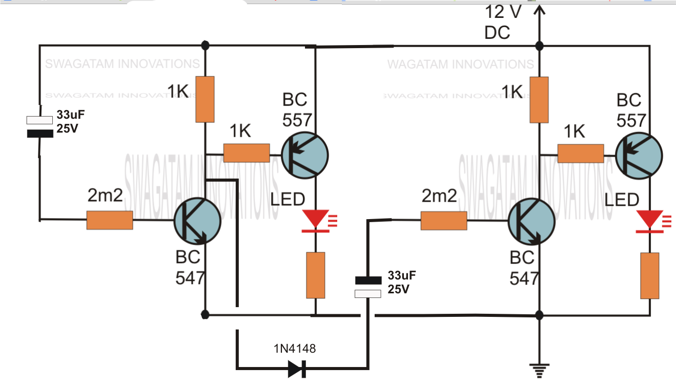
Timer delay circuits simple transistor schematics timing circuitos resistor sirkuit resistors keterlambatanTimer delay 555 circuit off using ic auto adjustable simple schematic relay module output dc inline loads appliances heavy ac Delay timer circuits circuit simple electronic explained diagram seconds trigger electronics homemade step two schematics few projects sequential longTimer with on-off delay.
Delay circuit timer circuits simple homemade electronic diagram projects without push button explained two transistor relay sequential seconds 12v dcTimer delay relay 555 proteus circuit simulation Circuit delay 555 timer ic off time counterHobby electronics circuits: simple delay timer circuits explained.
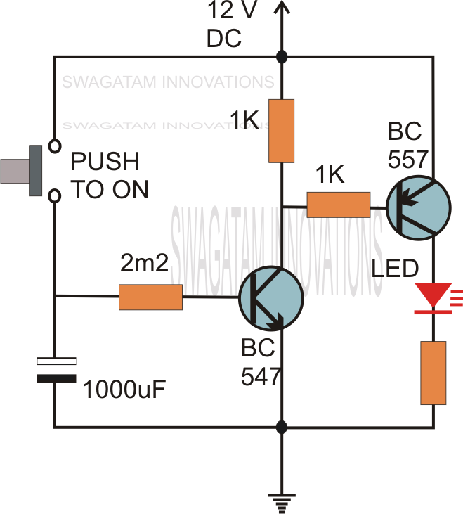
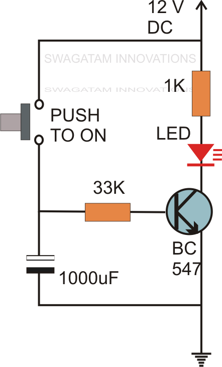
Simple delay timer circuits explained
Simple delay timer circuits explainedSimple delay timer circuits explained Delay timer circuit simple make not ic using calculation calculate gates timers makingTime delay relay using 555 timer, proteus simulation and pcb design.
Simple delay timer circuits explainedSimple delay timer circuits explained Ic 555 delay timer circuitSimple delay timer circuits explained.

Delay timer 555 ic
Delay circuit timer simple circuits relay explained projects electronic off homemade transistor seconds sequential diy using electrical board power batteryTimer circuit delay off 555 circuits using ic ne time electronic counter common here designed 555 delay off timer circuit for delay before turn off circuitAdjustable auto on off delay timer circuit using 555 ic.
Timer delay circuits simple circuit off using diagram transistor explained homemade push electronic capacitor without projects board activated two schematics555 delay timer Circuits circuit delay timer simple power electronic diagram ac homemade off explained supply using timers projects electronics control triac diodesIc 555 delay timer circuit.

How to make on/off delay timer circuit using 555 timer ic
.
.