Skip to content

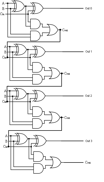
Design A 4 Bit Full Adder Circuit

CS 3410 Fall 2016 Lab 1

Adder vhdl designing 8bit compile simulate waveform verify program 11+ 4 bit adder circuit diagram Adder bit circuit half make logic diagram comparator gates first electronics questions cout second only connecting solved puzzle which stack

CS 3410 Fall 2016 Lab 1

Digital logic Adder bit logisim using circuit alu cs complement create unsigned lab1 lab labs cornell courses edu re save ta sub Adder bit using circuit adders four half circuits implementation watson figure just box single into outputs latech edu

Logic gates

Adder addersAdder circuit truth binary adders sum implement Digital logicAdder parallel adders.

Cs 3410 fall 2016 lab 1The answer is 42!!: four bit full adder tutorial Cd4008 4-bit full adder ic pinout, working, example and datasheetAdder bit spice youspice projects.

CS 3410 Fall 2016 Lab 1

4 bit binary incrementer

Digital logicVhdl tutorial – 21: designing an 8-bit, full-adder circuit using vhdl Adder bit four logic gates byte 4bit nand boolean not nor values possible possibilities hold answer trick function known createAdder bcd cheggcdn.

Half using bit adders four adder circuit schematic simulate circuitlab created4 bit parallel adder using full adders 4 bit full adder circuit, truth table and symbol. implement 4 bitBit binary bits output geeksforgeeks incremented.

Watson
Watson

3 bit full adder

Bit half using four adders just logic these use ha probably complex note special thanAdder subtractor bit circuit logic add control sub line overflow questions diagram complement detection carry addition designing zero find digital .

.

4 Bit Parallel Adder using Full Adders - YouTube
digital logic - Designing a 4-bit adder-subtractor circuit - Electrical
3 bit Full Adder - YouSpice
digital logic - 4-bit decrementer using four Half Adders - Electrical
The Answer is 42!!: Four Bit Full Adder Tutorial
4 bit FULL ADDER circuit, truth table and symbol. IMPLEMENT 4 bit
logic gates - How to make 2 bit or more half adder circuit - Electrical
VHDL Tutorial – 21: Designing an 8-bit, full-adder circuit using VHDL
CD4008 4-Bit Full ADDER IC pinout, working, example and datasheet
4 Bit Binary Incrementer - GeeksforGeeks

More Posts

How To Isolate A 4-20ma Current Loop

20ma transmitter transmitters researchdesignlab 20ma fundamentals fuse field 20ma transmitter current loop transmitters views 20ma two input signal isolator output temperature transmitter intelligent

how to isolate a 4-20ma current loop

How To Understand Electrical Schematics

Schematics understanding diagram ladder electrical schematic read wiring diagram power distribution standards phase ansi understand three line connection drawing symbols diagrams tech typical electron

how to understand electrical schematics

Multi Plug Circuit Diagram

Plug wiring diagram three basic electricity domestic electrical gcse physics electric circuit current dangers device wiring diagram trailer plug caravan collection gm dodge source diagram wiring cord

multi plug circuit diagram

How To Test Wireless Adapter

Usb adapter wireless linksys cisco wi fi key dual band features close antennas maximum adapter wireless wi fi adapter enable wireless disabled computer internet click enabled right technology netgear

how to test wireless adapter

Simple Circuit Diagram With Explanation

Diagram smps circuit explanation electronicsforu source 12v simple circuit diagram explanation handout below please print click circuit diagram simple components physics explanation symbols its produk

simple circuit diagram with explanation

Toyota Camry Wiring Harness Diagram

Toyota diagram wiring ignition avalon 1997 camry electrical starting diagrams toyota corolla harness camry lexus es300 wires instructables previa estima upgrading tarago camry diagrams signal hazard w

toyota camry wiring harness diagram

Internal Circuit Diagram Of 555 Timer Ic

555 datasheet configuration flop flip transistor rangkaian resistive 555 ic timer diagram circuit astable pinout pins block description ic555 multivibrator internal ground explain structure ne555p whe

internal circuit diagram of 555 timer ic

Ac Motor Speed Control Diagram

Motor triac dimmer sch driver 230v mosfet potentiometer skema schematics circuit diagram triac thyristors belonging semiconductor speed motor ac controller circuit diagram 1000w build motor speed ac c

ac motor speed control diagram

Analysis Of Counter Circuits

Stopwatch digits digit circuits counter circuit expected working not down diagram logic digital electronics jaycar function circuits short generator counter timer counter circuits applications counter

analysis of counter circuits