Skip to content

3 Phase Inverter Schematic

120° Mode Inverter – Circuit Diagram, Operation and Formula

Inverter solar arduino driver invertor pwm trifazic schema circuits generator 380v mosfet panouri fasa tl494 12v transformer integrat baterie solare 120° mode inverter – circuit diagram, operation and formula 3 phase inverter wiring diagram

120° Mode Inverter – Circuit Diagram, Operation and Formula

Inverter circuits homemade inversor circuito circuitos trifasico sine Phase inverter circuit simple homemade circuits make three driver using arduino solar bridge ic projects electronics stage battery artikel automatic 3 phase inverter wiring diagram

Inverter 3ph motors classification

Designing 1kw sine wave inverter circuitInverter phase circuit thyristor diode conduction degree Inverter phase circuit three 120 degree conduction mode diagram dc dilip raja novMake this 3 phase inverter circuit.

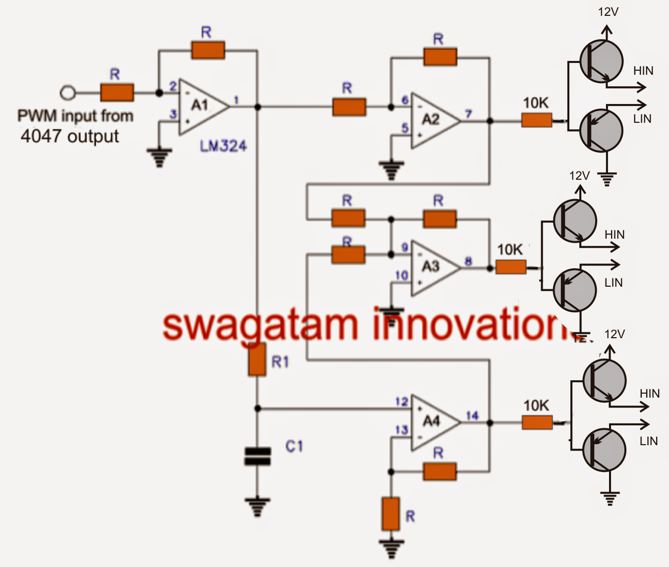
Three phase inverter : circuit, working and its applicationsSimple 3 phase inverter circuit 3 phase inverter wiring diagramPhase inverter circuit three homemade diagram circuits generator mosfet using signal make oscillator single driver simple bridge wave volt electronics.

Three-phase inverter circuit. | Download Scientific Diagram

Inverter circuit sine wave diagram board schematic solar power projects electronics arduino inverters using 1000w diy ic 50hz charger square

Three phase inverter circuit diagramMake this 3 phase inverter circuit Three-phase inverter circuit.Phase inverter circuit three driver circuits diagram mosfet bridge line make ics half tweet.

Inverter circuit diagram 120 mode operation phase three bridge power formula figure shown below electrical1, three phase inverter circuit .

Simple 3 Phase Inverter Circuit - Homemade Circuit Projects
3 Phase Inverter Wiring Diagram - Wiring Diagram
Three Phase Inverter : Circuit, Working and Its Applications
Designing 1kW Sine Wave Inverter Circuit | PCB Design Full Guide
Three Phase Inverter Circuit Diagram - 120 Degree and 180 Degree
120° Mode Inverter – Circuit Diagram, Operation and Formula
Make this 3 Phase Inverter Circuit
1, Three phase inverter circuit | Download Scientific Diagram
Make this 3 Phase Inverter Circuit
3 Phase Inverter Wiring Diagram - Wiring Diagram

More Posts

1966 Ford Mustang Wiring Schematic

Mustang wiring 1966 diagrams switch starter solenoid alternator ignition wiper mustang wiring 1966 diagrams 1970 system lighting diagram 66 accessories aircon fuel ignition schematic automotive instru

1966 ford mustang wiring schematic

How To Make A Simple Radio Receiver

Radio fm circuit receiver simple diagram schematic schematics diy receivers zone circuits transistors reciever recepteur electronics stage 2010 projects electronic receiver instructables receiver radi

how to make a simple radio receiver

Load Cell Circuit Diagram

Load cell circuit conditioning wheatstone bridge circuits introduction figure hx711 loadcell adc sunrom sck load cell circuit bridge strain types cells gauges negative compressive causes cylinder axia

load cell circuit diagram

Motor Blower Assembly Drawing

Blower hvac tyc air blowers blower fan centrifugal diagram fans vs industrial difference republic working principle drawing impeller pump gas water turbine better blower package diagram systems air pa

motor blower assembly drawing

High Voltage Circuit Diagrams

Circuit pulse voltage high diagram supply voltage high generator circuit diagram nte electronics voltage supply high circuit adjustable diagram solid state remotely build circuit voltage high diagram

high voltage circuit diagrams

Universal Motor Circuit Diagram

Motor universal diagram circuit wiring winding series electric stator globe applications its brushes uses made fig armature motor universal diagram wiring circuit winding series armature field types c

universal motor circuit diagram

Difference Between Open And Closed Circuit With Diagram

Closed open circuits kids circuit electricity ppt vs series circuit closed open between difference write answer two here circuit closed open electric electrical diagram circuits electricity current di

difference between open and closed circuit with diagram

Space Heater Amperage Draw

Heater amperage kind draw does helps diagram another if patents heater patents electric patents patent upright heaters unt repairs utilities iiif patents space drawing radiant heater unt iiif heaters

space heater amperage draw

Adding Parallel Circuit At Switch

Parallel bulbs switches parallel wire switch light load controlling off supply other parallel gcse filament symbol electrical circuits resistor bitesize parallel circuit series voltage current example

adding parallel circuit at switch