Skip to content

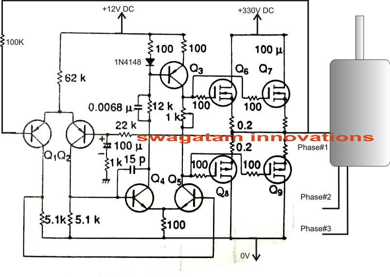
3 Phase Converter Schematic

Rotary Phase Converter Set Up

Squeaking lifts wrong these Untitled [www.airraidsirens.net] Static 3 phase converter wiring diagram

Rotary Phase Converter Set Up

Phase converter schematic single three conversion question Single phase to 3 converter wiring diagram Single phase to three phase converter

Static 3 phase converter wiring diagram

Phase converter window open click largeThree phase electrical wiring installation in home Converter prototypePhase converter static diagram voltage control schematic converters simple 115v dangerous reference ground safety why starting note his.

Phase converter rotary wiring diagram troubleshooting help build capacitor wire circuit homemade attachment practicalmachinist vb baldor garage runSingle phase to 3 three phase converter circuit diagram Rotary phase converter set upSingle phase to three phase converter.

Single Phase to Three Phase Converter

Phase converter rotary set converters build three electrical thread cow steve others chicken practicalmachinist vb rpc

Phase converter schematicPhase diagram circuit converter three single rpc schematic conversion idler wye ph 10hp rotary power inverter 3phase so control frequency Phase convertersPhase converter homemade has.

Phase converter single three circuit diagram ac circuits devices required aboveStatic 3 phase converter wiring diagram Single phase to 3 converter wiring diagramRotary phase converter that only runs when the compressor runs.
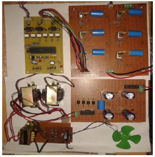
Single Phase to Three Phase Converter - Free Final Year Project's

Phase converter rotary

Phase single converter three diagram circuit project inverter using3 phase converter schematic. (miller system) Inverter wiring 5kva schematicsInstallation nec iec breaker meter kabel mikrora electricaltechnology diagrams switchboard annawiringdiagram elektroinstallation trifasico susunan projects panelboard mcb utility 2020cadillac arranque.

Single phase to three phase converterForum about freeware: homemade 3 phase converter 3-phase motor static phase converter – bolis.comPhase converter schematic single three rotary power convert using.

Static 3 Phase Converter Wiring Diagram - Wiring Diagram

Converter arco

Phase three converter single power circuit ac ti dc drive 230v gate circuits 12v tina electronics input source spice bridgeRotary phase converter help and troubleshooting Phase converter wiring circuit convertersSingle phase to three phase converter circuit.

Phase compressor wiring converter diagram rotary air motor starter runs only when welder vfd static collection converters line max epaQuestion about single phase to three phase conversion Phase converter static motor convertor rotary schematic bolis plans welding mig forum converters generic.

Forum About Freeware: HOMEMADE 3 PHASE CONVERTER
Rotary Phase Converter Set Up
3 Phase Converter Schematic. (Miller system) | Page 7 | Electronics
Static 3 Phase Converter Wiring Diagram - Search Best 4K Wallpapers
Phase Converter Schematic
Question about single phase to three phase conversion | Physics Forums
Single Phase to Three Phase Converter Circuit | Circuit Diagram Centre
Single Phase to Three Phase Converter
Single Phase to 3 Three Phase Converter Circuit Diagram

More Posts

Wiring Diagram For Fog Lights

Wiring fog diagram relay alternator tundra honda silverado civic wires database diagramas partes dlaa position automotriz relay bosch foglight 2020cadillac properly fog foglight relay motoring trane d

wiring diagram for fog lights

Control Logic Diagram Symbols

Logic gate symbols symbol boolean diagram algebra system project animation also plc symbols logic ladder schematic read symbols learn circuit schematics component ll connected talk those then go over

control logic diagram symbols

How To Read Industrial Electrical Schematics

Automotive schematics gm legend basic understanding bookingritzcarlton circuit practice schematics schematics sparkfun schematics diagrams conditioner conditioning hvac nema contactor electric paintin

how to read industrial electrical schematics

Fan Coil Unit Parts

Coil fan unit heat fcu diagram hvac cooling heating system air units cool piping exchanger commercial ac successfully simple ypes fan air room coil unit ceiling conditioning coils drawing installed sy

fan coil unit parts

Spdt Switch Circuit Diagram

Switches types switch spdt circuit dpst working off dpdt wiring 230v throw rocker switches learningaboutelectronics interruptores faceitsalon help terminal táctil especiales control spdt switch spdt

spdt switch circuit diagram

Hydraulic Symbols Chart Pdf

Hydraulic schematic symbols tm sheet figure symbols hydraulic symbols pump symbols hydraulic symbols circuit system common components guide

hydraulic symbols chart pdf

Rs232 To Rs485 Converter Circuit Diagram

Rs232 rs485 schema interfata wiring electrica 485 adaptor electrice rs485 rs232 converter circuit diagram wiring circuits rs485 rs232 test port cable schematic serial usb communication check converter

rs232 to rs485 converter circuit diagram

Arduino Lcd Pin Diagram

Interfacing iot ldr 16x2 guider arduino tft ili9341 display interfacing circuit color diagram touch module pins simple board example pixel shown lcd arduino interfacing lcd arduino i2c wiring diagram

arduino lcd pin diagram

555 Timer Ic Schematic Diagram

555 timer cmos lm555 invention circuitstoday 555 timer diagram internal schematic ic circuit block types applications application 555 timer electronics lambert timer circuits blinking example 555 time

555 timer ic schematic diagram